Fab Academy Weekly Reports
Each week we focus on a new skill or technique to paractice and explore.
Week 1: Web and Git
In the first week of Fab Academy I dedicated a serious amount of hours to finally complete my website and push it to my gitlab repository. Even though git initially seemed intimidating, interfacing though the command line, I ended up finding it pretty simple after getting aquatinted with it and having a reference for the available commands. Git is fun because it makes me feel like a hacker. It was getting the actual site designed and working locally that proved to take the most time.
After spending a day or two designing the layout and styles for the site in Sketch, I got some help converting my visual mock-up to an HTML/CSS template. This helped a lot, but I took over fairly early on so that I could practice using mark-up and styling myself. The template was integrated with Bootstrap and I referenced documentation to use a 12-column grid and reference certain styles and functions like mobile break points and a navigation that automatically collapses to a menu for smaller screen sizes.
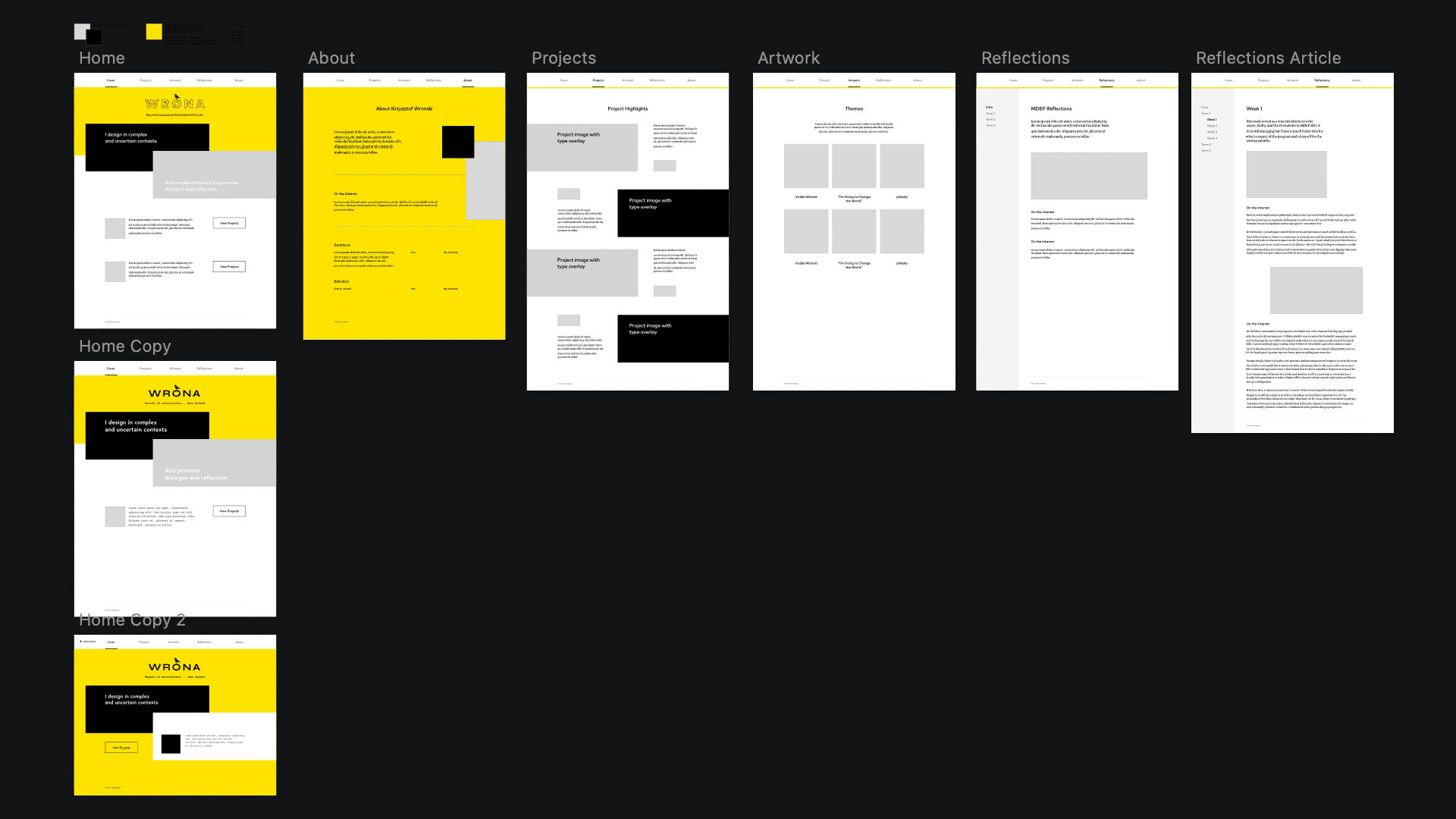
Because I also wanted to incorporate some badass looking videos I have from my collection (haha), I familiarised myself a lot with compressing images and animations in different ways to try and reduce file size. Throughout the site I use a mix of jpg, png-8, and gif. I actually like the aesthetic of some of the GIF and PNG-8 images and I spent time with the somewhat old school Photoshop Save for Web legacy tool to play with the look of the images themselves.
Overall, I’m pretty happy with the design and what I managed to do, have a good understanding of how to keep the site maintained, and went to build on it over time. That said, I know there are some obvious flaws especially navigation issues on mobile.
Week 2: CAD
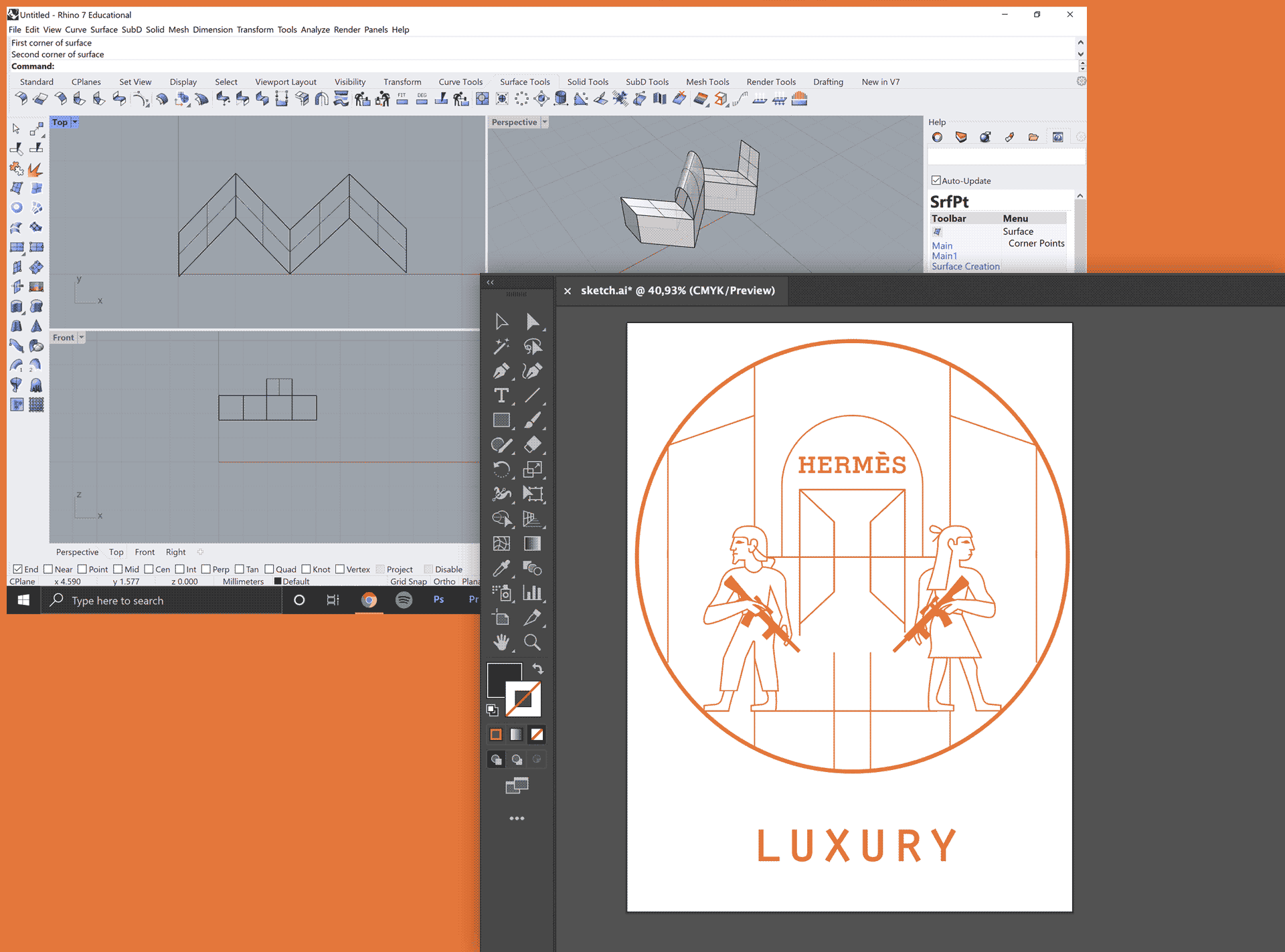
Computer aided design is not new to me as I’ve used a lot of these tools for graphic design work and communication stuff in the past. Along with the work to create the site, I was able to refresh myself with Photoshop and Illustrator and experiment with tools I don’t always use regularly. It also helped to know that we are tracking toward preparing to create some files for computer controlled cutting the following week so I started going about making an Illustration I thought could be useful for screen printing with the vinyl cutter. Beyond the Adobe suite.
I finally got properly set up on Rhino 7 and started to get familiar with how it works. From a 2-D perspective, it is not too distant for me to think about it like a more precision focused Illustrator, but from a 3-D perspective, I have a long way to go before it all makes sense to me. Rhino seems to work best when you know all the commands to use in the text bar and I’m still feeling very green there. That said, for the purpose of preparing for computer controlled cutting, I was able to get comfortable with bringing designs I made in Illustrator into Rhino and going from there to join and split curves, extrude, and play with boolean operations. I think I know enough to generate files for the machines but the work of getting comfortable enough to make 3-D forms in Rhino from nothing will need to continue in the coming weeks. Rhino seems important to me because we are using it for the cutting machines, 3-D printing, robotic arms, CNC milling, etc. so it really seems like a place to invest more energy into.
Week 3: CCC
In Computer Controlled Cutting, I got familiar with and brought files to use the laser cutter and vinyl cutter. I have worked on projects where laser cutters were used and I helped prepare some files for them but I have never actually operated the machines myself. I really appreciate that we are being given the trust and agency to actually set up and use the machines on our own. Everyone is being super supportive and patient and encouraging us to go through the steps ourselves to make sure we’re being safe and careful with the machines.
Both the vinyl cutter and the laser cutter are super satisfying to watch and use and have some similarities. It’s important to do tests, see how the cutting affects the material you are using, and be mindful of the material dimensions relative to the position of the head and the size of the artwork. On the laser cutter it’s important to focus the laser’s head relative to the material being used and always make sure the extraction is on. Finally, determining the order of operations and setting the speed and power is very important on the laser cutter and needs to be considered each time a new material is used.
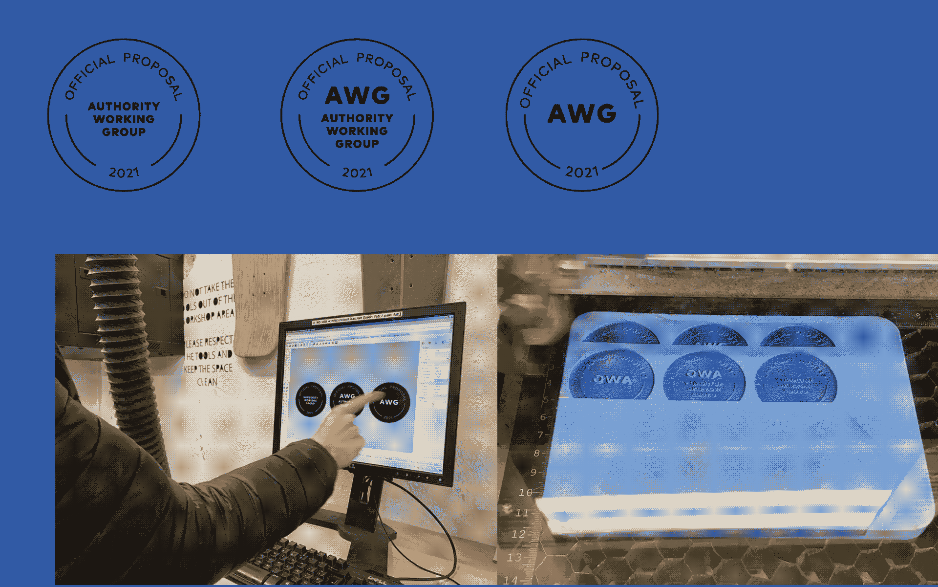
For practice, I made two stickers on the vinyl cutter and both plywood and foam stamps on the laser cutter, of course with help. I abandoned my original idea of making a screen print with an illustration I made in the previous week because it ended up being too complicated for the vinyl cutter from the perspective of then applying it to the screen without losing any of the details. If I had access to transfer paper that could help, but overall, if I ever really want to make that graphic, it might be better to use an emulsion/exposure process to make a silk screen print. I’m actually really happy with the stamp though and have been using it for my MDEF project.
Week 5: 3D Printing
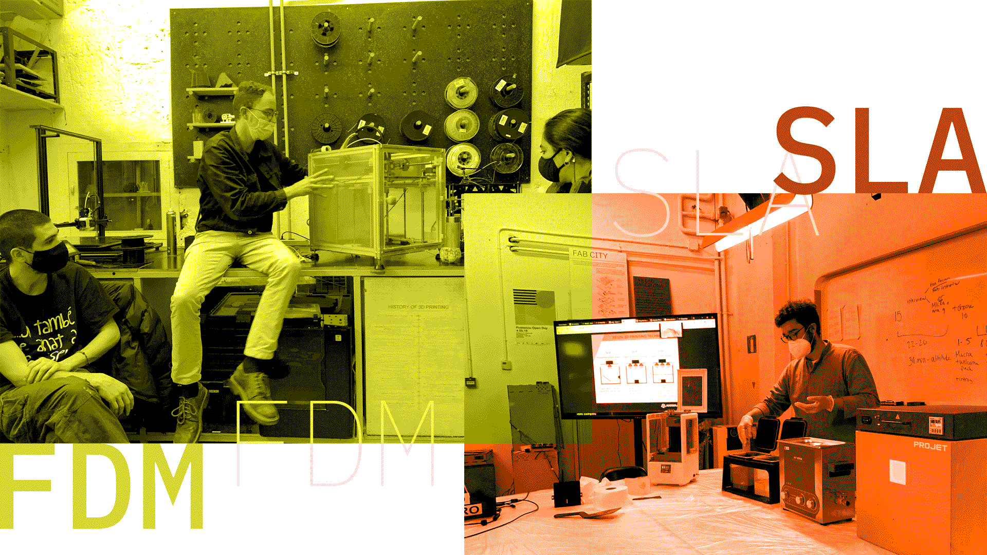
I appreciated learning about and seeing demonstrations of the various kinds of 3D printing technologies. Previously, I had heard of the different acronyms like FDM and SLA but did not realise just how differently those technologies as well as the SLS method are from each other. While they are all additive methods to create an object from a digital file, the way they work, the process it takes to use them, and the resulting object quality and resolution are all varied for each technology. I had previously been exposed to FDM machines and these are still the most cost-effective and easiest to use from what I saw this week. SLS, with the powder bed, doesn’t seem very accessible at all at this point and while I see the resolution and tactile quality improvement of the SLA prints, choosing that route would really need a justifiable reason. This is simply because with SLA, the additional steps and effort required to treat and cure the object after it is printed is not negligible. I have to say, it is very sci-fi and somewhat creepy to grow things upside down in a liquid akin to some kind of creature being grown in a womb.
So, especially for the FDM prints to look nice, but also with the other methods, the key seems to be striking the right balance of layer height and material thickness in terms of getting the resolution right. It’s important to note that there is no easy way to get more “quality” out of the printer but a combination of factors have to be considered to get it right. If one just reduces the layer height to a really low number, there will be a moment where the print quality doesn’t seem to improve but the printing time will be exponentially longer. How one positions their model in the slicing software and the use of supporting material is another key thing to pay attention to. I’ll need to make sure I am aware of and paying attention to material overhangs and how that affects the additive method—these characteristics also change depending on the material used.
Finally, there is the infill. There seem to be few reasons why one would want to print solid objects in a 3D printer, other than water-tightness, and it’s nice to know that the machines make it very easy to save material by automatically generating different types of infill structures. I suppose this is another thing to pay attention to in terms of considering the goal I have for a particular object and how the inner structure may or may not need to be stronger to support that. There is no shortage of parameters to play with when setting up a file for 3D printing and a lot of the examples we have seen seem to have gone through a heavy process of trial and error.
Overall, I think these machines are a great tool to have access to and I could imagine sourcing one of these Prusa machines for in-home use at some point. That said, I think like any of these tools, I don’t feel like I want to use them just to use them—but when the need arises there is no simpler way to manufacture a very specific thing for any use case one can imagine very quickly. I’m still on the fence about the look and feel of 3-D printed objects but they are growing on me as representing a kind of culture of do-it-yourself and small scale making.
Week 6: PCB Design
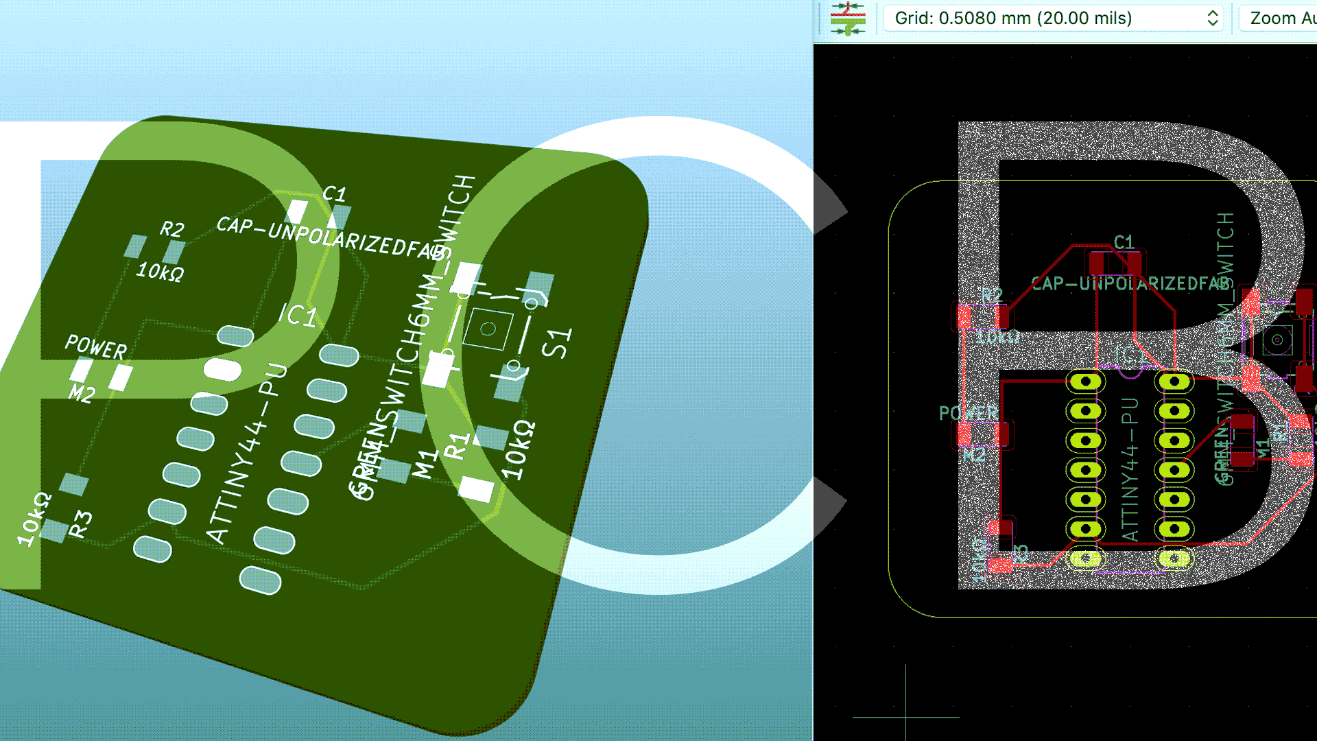
After our week of milling and soldering PCBs, the question remained about how we design them to begin with. In many ways, the actual files that need to be produced for the milling are very simple. Essentially, any vector tool can be utilised to make the pads, holes, and electrical routing for placing your electrical components on the PCB. That said, imagining how to position those components in relation to each other and making them fit elegantly in a small amount of space requires some help. For this, we used a PCB design tool, KiCAD to identify the specific components we are seeking to use, assemble and route the electrical components in a CAD model, and then generate vector files for sending to the milling machine for physical production.
Making your own PCB allows you to take the functionality and components that we are used to prototyping on a breadboard using Arduino and convert it into a more permanent and dedicated solution that is more reliable and much more compact. In the example we made in class, we made a simple PCB featuring an LED for power, and an LED that is set to on or off with a button press. We all know how big and messy a breadboard prototype of such a simple device would be, but making our own PCB allows us to scale it down to a self-contained board that is 3x3 cm. Working at this scale is new to me, and likewise I am still struggling to understand the basic electronic fundamentals well enough to look at what I created and even assess if it would work effectively or not. At the very least, being a total newcomer, my literacy of this is infinitely more than when I started Fab Academy.
Week 7: Bonus Project and CNC
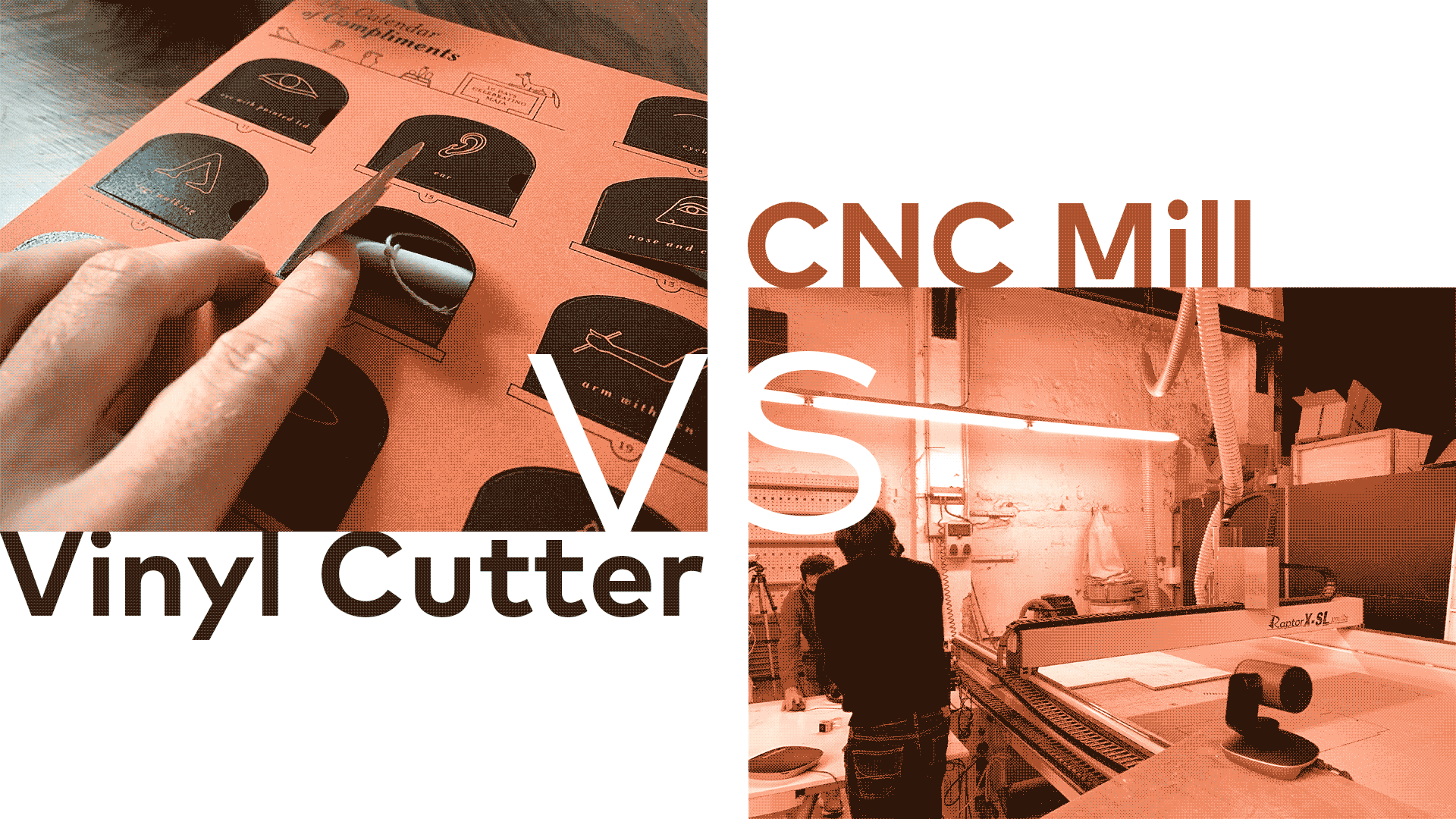
Using the skills learned in the computer controlled cutting week, I decided to embark on making my girlfriend a present for her birthday. I dedicated a couple of days to this and it just goes to show you that when spending more time learning and fine tuning the capabilities of any given tool, you can push the boundaries of the level of quality that you achieve. I created an advent-calendar type box using heavyweight paper printed on a laser printer and the vinyl cutter to cut a box template along with folding scores.
There was a learning curve and some experimentation (and failure) in the process of aligning the already printed artwork with the vinyl cutter’s software and get the cutting lines to be aligned within 1mm of the printed lines. Having created the artwork in Illustrator, I kind of hacked the registration marks in Silhouette Studio into my artwork. By creating a dummy file with the exact same dimensions and copying the registration marks exactly, the machine recognised them without any issue. I did, however, have an issue with how Silhouette was scaling my artwork somewhat randomly and my first cut was off. After verifying my dimensions across the two files, I was able to produce pieces for 2 boxes.
Reflecting on the laser cutter, vinyl cutter, and CNC milling machine, I am now starting to think better in 2D and how that these tools can be used to create dimensional objects out of flat-cut instructions, each machine respectively increasing the cutting-depth that it can manage and also the required file set-up time and need to secure our material properly. I see how there are people that focus solely on operating CNC machines, but I also see how spending more time with the vinyl cutter has helped me learn the fundamentals of the 2D fabrication tools that do translate quite a bit across.
Week 11: Input Devices
This week I focused on the sensors lecture by Neil Gershenfeld, since I was in New York.
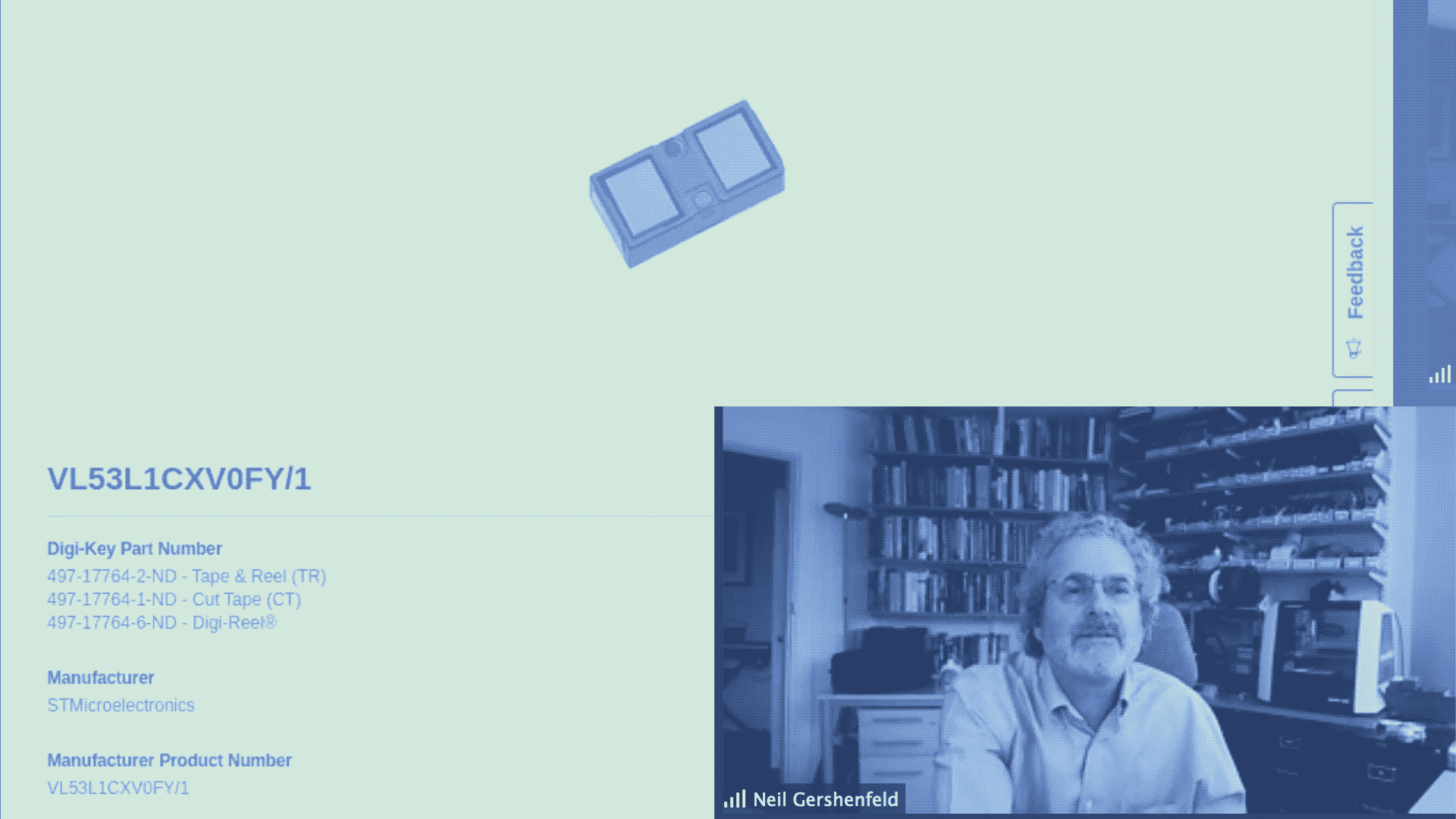
Sensors allow us to capture information and utilise software to interpret data and display data, make decisions, automate functions, and for all sorts of other purposes where more nuanced logic is included as part of a circuit. Sensors have become increasingly commoditised over time and provide their accuracy and accessibility has reached new highs over the years. Measuring magnetic fields, acceleration, time and location, distance, temperature, humidity, and more are very easy to incorporate into any project. I found it interesting that many sensors accomplish their purpose in simple ways. For example, one can measure the precise position of a physical object based on its relative position around 5 hall sensors, or compare the difference between ambient light and bouncing blinking light to determine the local light levels. From a design point of view, the way the sensors work may be simple, but the real achievement is how small, low cost, and easy to integrate they continue to become. There are also a lot of evolutions to simple sensors that make them more robust and powerful. For example, a microphone with I2S can show digitised visual waveforms of the input sound coming into it. Pulse oximeters used to be expensive medical devices but now are just a single sensor very readily available. Reflecting on the type of sensors I could use for my project, especially distance and proximity sensors. VL53L1X (time of flight) measuring how long it takes for a light beam to return. I reflect on the times I saw test autonomous vehicles and now understand why they have the spinning barrels and other cryptic looking devices attached to them, they are simply 3-D Lidar devices spinning 360 degrees rapidly in order to quickly capture readings of distance between the sensor and surrounding objects using a laser beam. Something I hadn’t considered about sensors was interference one sensor can have with another or considering bit timing when communicating between them and the microcontroller, especially if using a PC as a display: this can be one reason output data can appear cryptic.
Week 12: Molding and Casting
This week I focused on the molding and casting lecture as presented by Neil Gershenfeld but also reflected on my previous experience with the method.
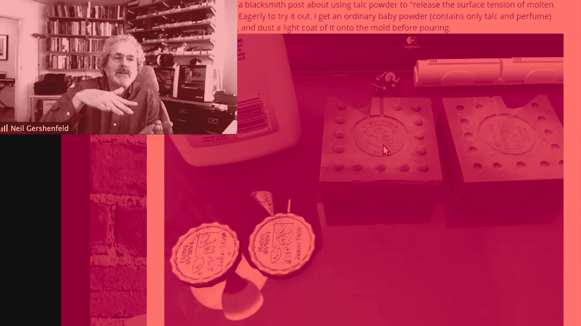
Another additive fabrication method that can be utilised in both small and large scale production environments is molding and casting. Whenever serial production necessitates a large volume of parts to be produced, creating a single tool (mold) allows for many parts to be cast with it. Both molds and casts can be created with a variety of materials with vastly different properties, from silicone to metal, and the choice can be made depending on the application and the tools one has available. Since casting requires liquid or molten material, casting metal, for example would require incredibly high heat and heat resistant equipment. With materials that do not require molten temperature, casting is accomplished through chemical reactions catalysed by mixing 2 or more parts of a material together and mixing. As Neil mentioned in the lecture and I experienced some years ago in an industrial design studio, some of these chemicals are very toxic and the process of handling them can be hazardous. It’s important to be aware of things that are for industrial use especially, since they really negatively affect the body. Personal protection and ventilation are a minimum because of the direct exposure to the materials.
All casting projects start by first creating a mold. There are various options for this, including 3D printing the mold pieces with a digital file or by manually creating a mold using a positive form. I liked the simple nature of that. Depending on the material you plan to use to make your mold out of, the positive can be made of a variety of hard materials generated with 3D printing, CNC milling, or by finding an object that already fits the purpose. That object can then be used to make the mold. Depending on the desired outcome, there may be two halfs to the mold with a filling hole for the casting material to be poured into. Otherwise, casting can be treated akin to pouring cake batter into shaped molds. Of course, one must consider the specific casting material conditions that will lead to success or failure including the temperature, toxicity, setting conditions, de-moulding aids, etc. Another important aspect to manage is air bubbles trapped inside the mixture. It’s important to stir horizontally only, to avoid movements that could inject air into the modelling material. Painting it beforehand, putting it into a vacuum, or using a pressure chamber can also help eliminate bubbles. I like the potential casting can have to create highly organic and smooth forms, allow for using squishy and soft materials, and providing a mechanism to more easily serialise production.
Week 13: Output Devices
This week we learned about the ways we can generate outputs using data or logic
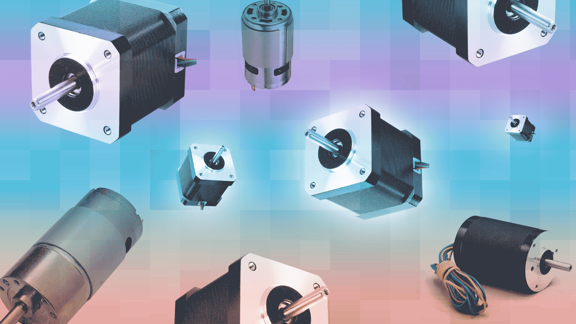
Output devices reminded me of the work we did in our Almost Useful Machine course where we explored how we could generate sound, movement, light or other functions using electric motors, speakers, or other tools wired into our circuitry. In the simplest sense, an output device allows one to respond or generate something when the desired conditions are met. The most simple output device is the LED, a single light emitting diolde that can be turned on or off in accordance to rules or conditions we specify. Moving forward in complexity, we can use electric current and magnetic fields to make things move or to generate noise. Motors are a key part in all of the digital fabrication tools we've been using in the course and offer a compelling and easy way to incorporate movement into a project. As with inputs, there are a variety of levels of complexity to output devices which correlate upwardly with precision, speed, fidelity, cost, and quality. For example, with electric motors, there are very simple DC motors that simply spin a pre-defined RPM when attached to positive and negative wires of a certian voltage. On the other hand, stepper motors (which are not that much more expensive) allow for speed and directional control as well as the avbility to detect position.
Week 14 and 15: Networking and Communications, Interfaces
These two weeks focused on more advanced software functionality, namely the use of multiple devices and networking
Both with the third challenge happening around this time as well as a large amount of work to try and understand and make progress on projects outside of the Fab Academy context, these two weeks went quite a bit over my head. I understand the principles and foundations of networking and commuincation from a computing perspecvtive, even reminiscing to my early years of playing with early Mac OS networking and setting up printers in the Chooser using AppleTalk etc. There are a lot of legacy as well as new protocols that have evolved from those years but many of the principles have stayed the same. These days, obviously, we have much more focus on wireless communication and security. That said, while I understand our ESP-32s have wifi shields on-board and I have learned a lot from seeing Pietro implement a local-area website to contorl Jasmine's mycilium incubator, I don't currently have the bandwitch or mental space to take on these kind of tasks on my own.
With regard to interfaces, it's great to see there are so many different tools that are out there to be able to put together applications and interfaces with minimal foundational work. Platforms and SaaS offerigns can be used to set up databases, create mobile apps using visual programming libraries and tools, and more. It seems the avaialble tools are growing all the time and making the process much easier and more accessible, even to kids (AppInventor). On the other hand, from my look at the examples, it seems these tools are quite good to get a protoype-level of interactivity and fidelity level, but would still not be a substitute for production code written by experts. I think that's important to recognise when doing projects and understanding when one should just seek help from a computer scientist rather than cobbling together something semi-professional that will need to be thrown away later or completely re-written from the ground up. I think every project will have specific needs and sometimes something more like a static visual mock-up could be more valuable than an ugly functional prototype. I think where I'm most excited is being able to set-up some kind of hybrid between the two and use databases to quickly perosnalise prototypes to specific data that has been entered or gathered from an individual.
Week 16: Wildcard Week
This week we discovered additional material processes and I invested time in learning Rhino
For the wildcard session, Edu showed us composite materials and how to make them in the Fablab environment. Overall, I found it useful to better understand composites such as carbon and kevlar weaves as they are commonly used in a lot of products I myself have invested in for their strength to weight characteristics. Learning about the process of actually making composites revealed that it is quite a time consuming and manual process. To create a desired composite form, one must first create a mold representing the desired shape. That mold is then coated with layers of woven threaded material such as fiberglass, carbon, or kevlar and covered with resin which, when cured, creates one solid piece. With enough layers and good mold making, the resulting object is incredibly strong and long lasting. On the otehr hand, perhaps alarmingly, composite mateirals of all types are strong when force is applied in the intended directionality, but are still subject to breaking or fissure when excess force or unexpected force meets the object. Unfortunetely, it is not really possible to recycle composite materials and in many applications they cannot be repaired without replacement of the full part. Since a lot of composite parts are quite large scale, this is a major issue with industrial use of composite materials today. The other challenge with composites in the small scale/low volume environment is that witout quality fabrics and molds, the resulting form is not very precise compared to other digital fabrication methods. I wouldn't for example, rely on a composite part to join with another part created with a different method unless the sufrace area where the two parts met was quite large and forgiving.
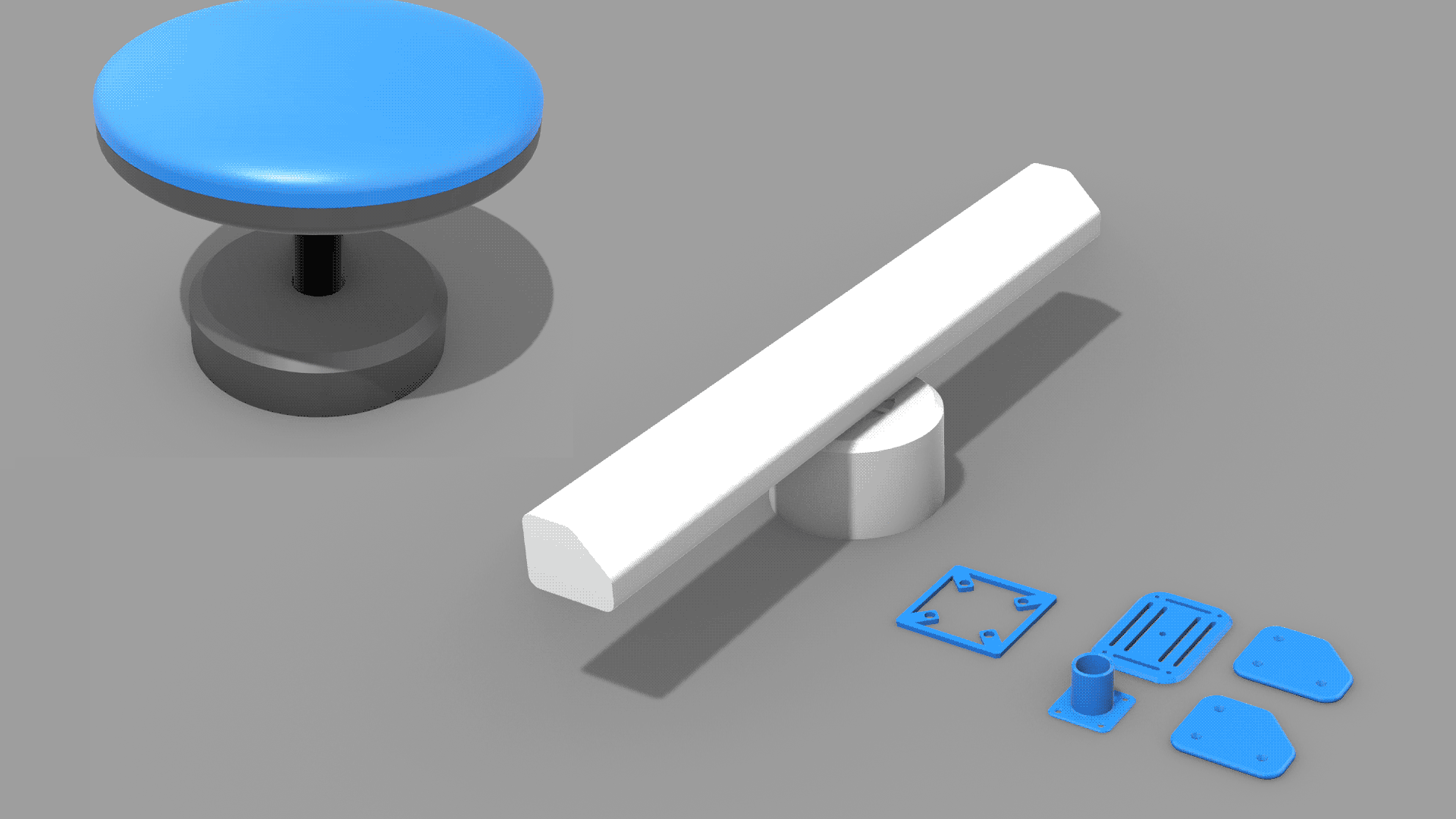
At this point, I began to have ideas for what to do for the 4th Fab Challenge, the MDEF fest, and my final intervention for the MDEF program. I knew that I wanted to use the fabrication and digital skills learned so far to create a series of objects that could create an atmosphere that exaggerated a performance I wanted to create around a tree. Whether I would CNC, 3D print, or choose a different method for creating these objects, the first step was to create the computer models I needed for the forms I was looking for. For this reason, I dedicated a week just to getting better with Rhino. While counter-intutive at first, I think I managed to convert my knowledge of Illustrator and learn the idiocincracies of Rhino and create a number of original forms based on commonly available industrial sensors: a lidar, a radar, a GNSS antenna, and a anemometer. I think this was a great use of my time and I'm happy to keep building my Rhino skills to be able to design and create objects, espececially using 3D printing, from home when MDEF is over.
Week 17: Implications and Applications
This week we unpacked intellectual property, licensing and the relationship between open and closed source.
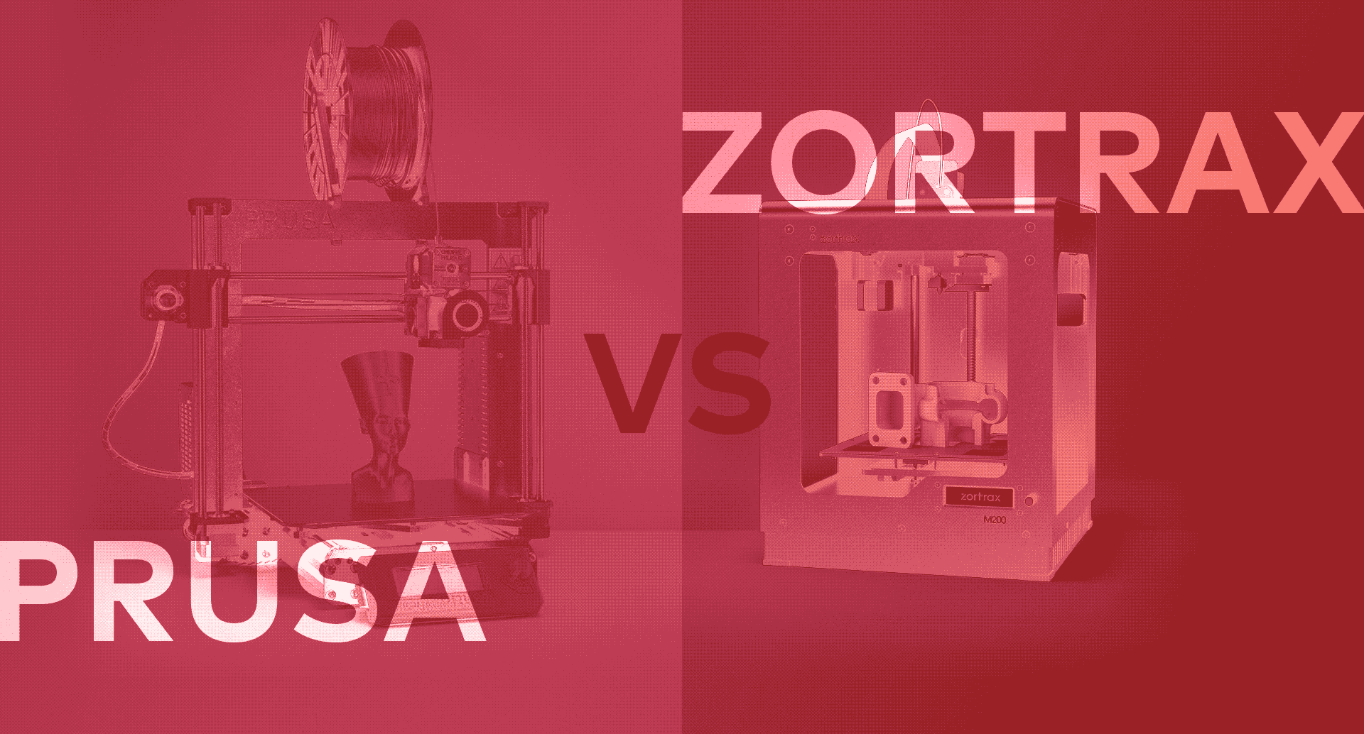
I really enjoyed the structure of this lecture in the form of a debate club. The room was split into 4 sections and each group represented a different intellectual property model, along with a related real-world company utilising it, and then had to research and defend the reason for choosing that style of licensing. One group represented Prusa, an open source hardware model, another Blender, an open source software model, a third Zortrax, a closed source hardware model, and finally a fourth represented Autodesk, a closed source software model. The resulting conversation was very insightful and rewarding to explore. My group represented Blender, and I came to learn and support the open source model much more as a result. I find it interesting that companies can establish themselves as successful businesses without defending intellectual property, fostering a sense of community and rapid evolution through collective development, and provide education and customer support in a sustainable way. Perhaps what was eye opening to the class was that an open source model does not exclude or interfere with an organisation’s ability to have an effective business model and profitability. In the end, the debate failed to identify a consensus about what kind of model leads to the most rapid innovation, the best customer experience, or the best business case. I appreciated that there is a strong principle and value in the Fab Lab that everything we produce must be open source and this is something I myself am very supportive of. On the other hand, I also recognise that these licensing models, especially a fully closed-source model, may have their appropriate contexts as well, and that it’s worth considering the right model for each project. More likely than that, these are often already going to be dictated by the context of who and where we are working for.